

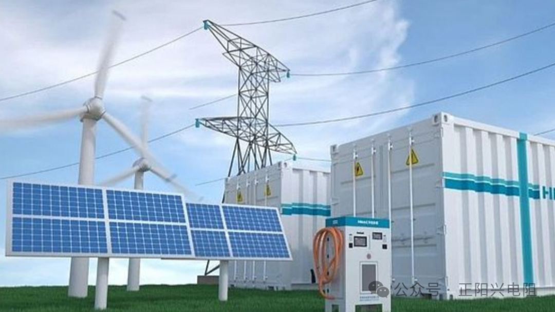
In energy-storage systems, the pre-charge resistor is an indispensable component that protects core devices such as inverters and contactors. Our previous article explained why pre-charge resistors are deployed in energy-storage equipment. We learned that the pre-charge circuit suppresses inrush current at power-on and prevents component burnout caused by direct closure of high-voltage capacitors.
However, many engineers are often confused during practical projects: what are the appropriate resistance value and power rating for a pre-charge resistor? Improper selection may lead to slow pre-charging that reduces operational efficiency, resistor overheating, or unexpected tripping under inrush current, bringing risks of component failure and even safety hazards. Combining key factors including energy-storage operating conditions, load capacity and pre-charge duration, this article presents a complete selection workflow and practical guidelines for pre-charge resistors, offering references for system design.
1. Total Pre-charge Energy
The total energy stored in the rear-end DC-bus capacitor is the energy to be absorbed by the pre-charge resistor.
Formula: E=0.5*CV2
C = Total capacitance of the DC-bus capacitor
V = Rated high-voltage of the system
The resistor must withstand this pulse energy. Insufficient energy-handling capacity will result in immediate burnout or rupture.
Example: Assume the DC-bus capacitance = 60 mF, battery-string voltage = 800 Vdc.
E=0.5 × 0.06 × 8002 = 19200J
For this system, the energy rating of the selected pre-charge resistor must be ≥ 19200 J. Otherwise the resistor will burn out immediately upon power-on.
Note: A safety margin is required in real-world engineering. Do not select a resistor rated exactly at 19200 J. A safety factor of 1.5 ~ 2 times is recommended.
2. Resistance Value (R) Selection
The resistance directly determines pre-charge current and pre-charge time. Before selecting resistance, define your target pre-charge duration, then calculate the required resistance.
1. Current-side analysis (I=V/R): A smaller resistance yields a higher initial inrush current and fails to achieve current-limiting.
2. Time-side analysis: Approximate pre-charge time t≈3RC. A larger resistance slows down capacitor charging.
| Time Constant | Voltage Charged Percentage |
| 1 τ | 63 % |
| 2 τ | 86 % |
| 3 τ | 95 % |
| 5 τ | 99 % |
Example
DC-bus capacitance = 60 mF, battery-string voltage = 800 Vdc. Target: charge the capacitor to 99 % of battery voltage within 2 seconds. 5τ = 2s, τ= 2/5 = 0.4s. R=τ/C=0.4/0.06≈6.67Ω. A 6.8 Ω pre-charge resistor is suitable in this case.
Practical selection principle: Choose a proper resistance value within the permitted pre-charge time window, balancing current-limiting performance and startup speed.
3. Instantaneous Peak Power
Instant power at power-on: P=V2 /R. This is a short-duration pulse power (lasting only several seconds), not the continuous rated power of the resistor.
Critical Reminder: Do NOT select resistors solely based on continuous power rating. You must evaluate the short-time pulse overload capability.
4. Pre-charge Time Requirements
The BMS is configured with a pre-charge timeout protection threshold (typically hundreds of milliseconds to several seconds). The RC time constant governs the voltage-rising speed. The DC-bus voltage must reach ≥ 90%-95 % of battery voltage to finish pre-charging before the BMS timeout limit.
5. Temperature Rise & Heat Dissipation
Even though the pre-charge process lasts only several seconds, massive heat is released instantly. The resistor surface temperature rise must not exceed the component maximum operating temperature.
6. Component-Level Characteristics of Resistors
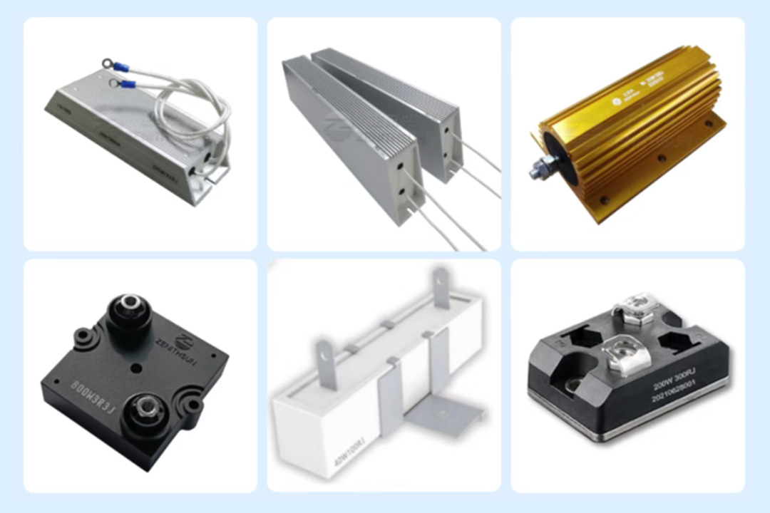
1. Resistor Type: Aluminum-housed pre-charge resistors and thick-film power resistors are widely used for energy-storage applications.
2. Resistance Tolerance & Drift: Low resistance drift is required.
3. Withstand Voltage: The resistor’s voltage rating must exceed the system’s maximum DC-bus voltage.
7. Operating-Condition Safety Margin
Perform calculations based on the fully-charged maximum battery voltage, not merely the nominal voltage. Derating design: A 1.5-2 times safety margin for energy and power is suggested.
8. Logic Matching with BMS
The standard pre-charge completion criterion: DC-bus voltage reaches 90%-95 % of battery voltage. After selecting the resistance value, back-calculate the actual pre-charge duration.
The Importance of Reliable Pre-charge Resistor Manufacturers
★★ Parameter calculation and selection are only the first step. Reliable supply-chain support is equally essential. ZENITHSUN has specialized in power resistors for 22 years, supplying pre-charge resistors to many leading energy-storage enterprises.
About Us
Shenzhen ZENITHSUN Electronics Technology Co., Ltd. was founded in 2004. It is a leading domestic manufacturer of power resistors and load banks. With nearly 30 years of R&D and market experience, we supply a broad product portfolio including Aluminum-cased resistors, braking resistors, pre-charge resistors, and more. Our products have been exported to 56 countries and regions across Europe, North America, South America and Asia.


